By Filip Rochette

Introduction
A major manufacturer has developed an innovative ion exchange system for the removal of nitrate from groundwater sources. These systems have become the leading nitrate removal technology in the United Kingdom, with over 50 percent of nitrate removal plants installed in 2006-09. This article describes in detail the system process.
Many water utility companies are experiencing ever increasing levels of nitrate in drinking water sources. Utilities that are heavily dependent on groundwater sources beneath arable land are particularly badly affected and in danger of breaching legal limits in many cases. Agricultural sources of nitrates are by far the most common. Fertilizer runoff, farm-animal wastes and septic tank discharge all percolate through the soil into groundwater aquifers, and ultimately contaminate water supplies. Other sources of contamination are industrial in origin, and include chemical manufacturing operations and cutting oils that contain nitrates. Sources also occur naturally and include atmospheric precipitation (as ammonia), local mineral deposits, such as potassium nitrate (saltpeter), and nitrogen-fixing bacteria in decomposing plant matter. The overall contribution made by natural sources, however, is small compared with that from human activities. In Europe, the maximum allowable nitrate concentration in drinking water is 50 mg/L (EC Nitrate Directive 1991), while the US EPA limits the allowable nitrate level in water to 10 mg/L measured as nitrogen, or 45 mg/L measured as nitrates.
Traditional ion exchange systems incorporating nitrate-selective resins have been used to remove nitrate. These produced a variable treated water quality, sometimes needing pH correction and intermittent high volumes of high-strength effluent, which typically must be stored onsite and then disposed of gradually to sewers or tankered offsite for processing (usually at the nearest large sewage treatment works). During the last decade, RO technology has been used in preference to ion exchange, as it produces a continuous stream of low-strength waste, which is in some cases easier to dispose of. RO is less efficient, however, in that it produces a larger volume of waste (typically between five to 20 percent of the treated flow), and is extremely energy intensive due to the use of high-pressure pumps (see Table 1).
A typical nitrate removal RO system with one-stage treatment (80-percent recovery) at 16-barg (240-psi) operating pressure would require 0,6-kWh-per-m³ produced water, while ion exchange systems require less than 0,1-kWh-per-m³ produced water. Ion exchange systems use low-pressure pumps (three-barg [45 psi]), which reduces electrical power consumption. As water resources become ever more scarce, the focus has returned to improving the efficiency of the traditional ion exchange process. The continuous countercurrent ion exchange system is an improvement on the conventional ‘batch’ system, producing less waste and more consistently treated water quality.

Process description
The nitrate removal system uses conventional approved nitrate-selective resin (several resin suppliers are available with NSF or similar regulatory approval) to adsorb nitrates from raw water, but the mechanics of the system are unique. Standard gel-type or macroporous strong-base resins are capable of removing nitrate ions; only performance will be influenced when sulphate concentrations are equal or even higher as nitrate concentration.
HCO3– < Cl– < NO3– < SO4–
(Standard resin)
Nitrate-selective resin will have a much higher affinity for nitrates over sulphate, which ensures the necessary reduction in nitrate levels.
HCO3– < Cl– < SO4– < NO3–
(Nitrate-selective resin)
Traditional ion exchange systems operate large-duty/standby columns, and raw water is passed through until the bed requires regeneration, at which point it is taken offline. Instead of using large-duty/standby resin beds, the new system utilizes a series of smaller columns, improving efficiency of resin utilization. Bed depth and volume are designed so that the total contact time is kinetically sufficient for adsorption of nitrates and regeneration of resin to take place, while ensuring that pressure drops across the resin bed are sufficiently low to protect the resin.
The system is a true counter-current ion exchange system in which exhausted ion exchange resin is continuously taken offline, backwashed, regenerated, rinsed and returned to adsorption with all phases of the cycle occurring concurrently. The countercurrent process includes the configuration of the regeneration and rinse zones. The regeneration stage ensures a progressive increase in brine strength as it comes into contact with the exhausted resin, controlled by a patented valve system (described below). System advantages include elimination of downtime for regeneration and reduction of regeneration waste volumes, while maintaining consistent effluent and treated-water characteristics.
At the heart of the system is a patented multi–port valve (see Figure 1) connected to a number (usually 20) of resin columns (the size of the valve and the columns are dependent upon the size of the flow to be treated). The resin columns and the valve ports remain in a fixed position, while the valve’s internal process disc indexes at regular computer-controlled intervals to effectively change the position of each column within the process. Instead of requiring a turntable to move the columns, as with some alternative designs, the multi–port valve directs the flows to and from the appropriate columns.
A 360-degree rotation of the process disc constitutes a full process cycle, and the cycle duration is re-calculated by the PLC according to the nitrate load in the raw-water feed after every index. Each column remains in any one position for a fixed period of time, after which the valve process disc indexes, redistributing the various process flows to the 20 columns. The actual valve movement is typically 10 to 15 seconds and is termed a ‘step’. The ion exchange system is divided into four distinct zones, with each zone operating continuously. There are generally 20 columns in total, of which at anytime 14 are in the adsorption zone, one is in the backwash/displacement zone, three are in the regeneration zone and two are in the regeneration rinse zone. Although the number of columns contained within each zone does not alter, as the process disc within the multi-port valve changes position, each column will effectively be moved along one position in the process cycle. Therefore, by rotating the process disc at calculated intervals as described, each column is taken through the entire process. Following adsorption, the resin is backwashed, the hard water within the column is displaced and the resin is then regenerated and rinsed. As all zones are part of the continuous automatic process, the various process steps are carried out without interruption to the nitrate adsorption process.
Process details
The overall cycle of the multi-port distribution valve is shown in Figure 2. Column 1 is at the end of the 14-stage adsorption zone and almost completely saturated with nitrates, while Column 14 is at the beginning of the adsorption zone and barely loaded at all. During the next index step, the process disc rotates within the valve, redirecting the flows to every column in the system simultaneously. The valve itself and all the columns remain stationary, but as a result of the process, disc rotation Column 20 will pass from the backwash displacement zone into the three-stage regeneration zone; Column 17 will pass from the regeneration zone into the two-stage regeneration rinse zone; Column 15 will pass from the regeneration rinse zone into the 14-stage adsorption zone, and Column 1 will pass from the adsorption zone in to the single-stage backwash/displacement zone.

process cycle
Adsorption zone
Typically, the system has 14 of the 20 columns (or 70 percent of the total resin charge) dedicated to adsorption, with all of the adsorption ports connected in parallel configuration. In this zone, raw water passes down the column and nitrate anions are removed by attachment to the resin beads, displacing existing chloride ions. The chosen resin is primarily selective for nitrates, though other anions will also be removed to varying degrees; therefore, the nitrates are ‘adsorbed’ from the water onto the resin beads. The displaced chloride ions remain in the treated water, resulting in a small increase in the treated water conductivity by typically < 100 µS. Depending on nitrate concentration in the feedwater, and flowrate of the feedwater to the multi-port valve, the cycle time (360° rotation) will increase or decrease, thereby optimizing nitrate loading within the adsorption zone. The cycle time of the valve will be determined by the PLC/SCADA system; hence, no operator intervention is required to treat a large range of flows, even with variable incoming nitrate concentrations. As the multi-port valve indexes through the cycle, the last resin column in the adsorption zone (fully saturated with nitrates) enters the backwash/displacement zone.
Backwash/displacement zone
To prevent precipitation from occurring in the regeneration zone, a backwash/displacement zone is employed. This zone consists of one column (see Figure 2, Column 20) in which the potentially hard water is displaced with softened water in upflow mode, which also fluidizes the bed and backwashes any accumulated debris. Correct operation of this zone will reduce maintenance downtime to clean scaled equipment. This is the only zone configured for upflow, which serves two purposes. First, any organics or solids that may have collected on top of the bed during adsorption are readily flushed from the system. Second, the resin bed is fluidized to prevent channeling from developing inside a column, thus ensuring a uniform bed for each cycle of adsorption. The displaced hard water may be recovered by returning it to the raw-water feed, reducing waste volumes. This backwash eliminates the need to remove the resin from the columns for cleaning and the associated problems of maintaining the resin in a sterile environment. Following backwash/hard-water displacement, the multi-port valve indexes to the next stage of the process and the column enters the regeneration zone.
Regeneration zone
During regeneration, the resin is contacted with a brine (NaCl = sodium chloride) solution. Nitrates and other anions are replaced with chloride ions, returning the resin into the chloride form for re-use. The regeneration zone consists of three columns configured in series, thereby making full use of the countercurrent advantages; this improves brine utilization and allows for higher resin capacities. Countercurrent regeneration is utilized by contacting the fresh five to eight percent NaCl solution initially, with the third resin column (see Figure 2, Column 17) in the three-bed regeneration zone series. Brine continues to flow through the zone (from Column 17 to 18 to 19) so that the first column in the series (Column 19) is regenerated with the weakest brine. All flows within the regeneration and rinse zones are downwards. Waste produced in this zone predominantly comprises sodium nitrates, sulfates and excess brine and is usually disposed of through a waste-handling facility or directly to drain. A portion of this effluent can be recovered, thereby reducing the amount of softened water required and the amount of waste produced. Following another multi-port valve index, the fully regenerated column enters the regeneration rinse zone.
Regeneration rinse zone
The regeneration rinse zone uses softened water to wash out the remaining brine prior to the column re-entering the adsorption zone. This zone consists of the remaining two columns (15 and 16), configured in series with countercurrent operation, and is designed to prevent brine from entering the treated water. The softened water used in this zone flows through Column 15, followed by Column 16 and then to the regeneration zone (Column 17), where it is mixed with saturated brine to yield the desired regeneration concentration. It continues along the countercurrent regeneration path with the brine and leaves the process as a common single-waste outlet.
Results

In 2005, the first full-scale nitrate removal system for removing nitrates from water was installed for Thames Water—United Kingdom at Sheafhouse WTW. The plant has been in supply for almost five years and has been proven to easily meet its performance guarantees with regard to power consumption, waste production and chemical usage, all of which are considered to be low when compared to conventional nitrate removal methods.
There are currently 12 nitrate-removal schemes operating for UK-based water companies. A detailed description of the systems and a synopsis of the overall performance observed at various operational sites is given in Table 2. These systems have now been operating for almost five years under a range of flows and regimes and with a range of multi-port valve sizes. All schemes have been shown to operate reliably and successfully, resulting in client confidence at all levels. All sites were designed on predicted nitrate levels for 2015. Performance testing was done under present-day nitrate levels and extrapolated for 2015. Performance testing proved that treated-water nitrate levels were achieved consistently at all sites. Salt and power consumptions were demonstrated to be within design expectations, and waste volumes were well within design expectations, in some cases as low as 0.3 percent of total works flow.
Compared with traditional fixed-bed, pulsed-bed and counterflow IX systems, the subject system consumes 75 percent less water, while the volume of ion exchange resin required can be reduced by up to 50 percent, offering significant savings.
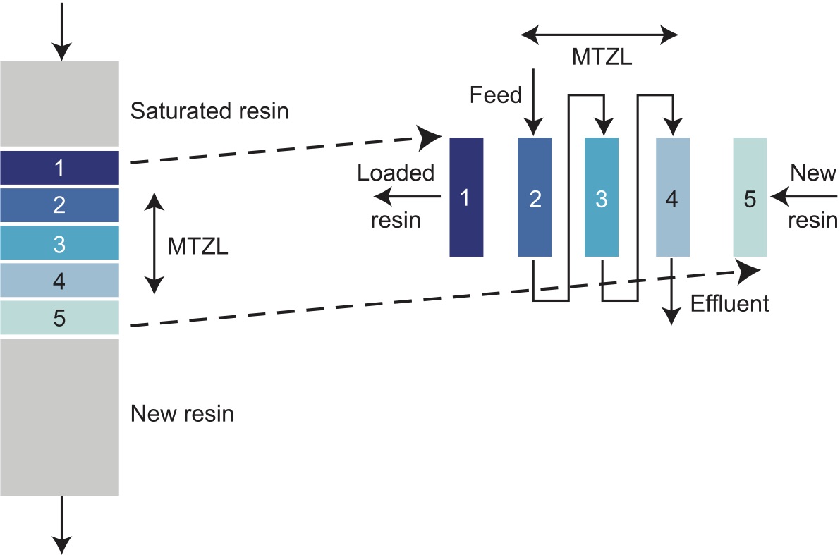
Figure 3 shows that most resin is in an active state, the volume of saturated resin or fresh unused resin is minimized. (MTZL = Mass Transfer Zone Length.)
Countercurrent fluid flow and recycling of rinse water to dilute the 28-percent sodium chloride feed, together with uninterrupted process streams, guarantee high levels of recovery.
Treated water quality
As part of the system analysis, continuous monitoring of nitrate levels is carried out using dedicated nitrate monitors. Target nitrate levels of treated and blended water are achieved consistently, with the plant responding quickly and effectively to fluctuations in raw water flow and nitrate levels. Fluctuations observed with treated water nitrate levels (Figure 4) are typically in conjunction with system startups and shutdowns. Telemetry data is used to confirm the plant is meeting its targets. Small regular fluctuations in treated-water nitrate levels are often common during the continuous process. The nitrate reading represents an average of the quality from 14 columns in the adsorption zone. If measured individually, those columns most recently regenerated would show lower nitrates than those about to enter the backwash/displacement zone.

(profile repeated on each index from the following column)
Waste stream
As seen in Figure 5, when a column first passes into the regeneration stage from the backwash/displacement zone, the initial fraction of outlet flow is softened water.
Following typically 10 to 15 percent of the index time, the brine breaks through into the waste stream, showing up as a sharp increase in conductivity. As the brine begins to exchange for nitrates, the nitrate level in the column outlet increases significantly. This high level of nitrate follows a steady decline as the column passes through the three regeneration positions. The end of the regeneration stage sees a sharp decline in conductivity as the brine is rinsed out of the column. There is potential to recover a fraction of the waste to the salt saturator. Any high levels of nitrates or conductivity entering the adsorption zone as a result of poor rinsing are highlighted via alarms, protecting the treated water product from poor rinsing. As the flow is countercurrent and the rinse dilutes the brine as it flows through the multi-port valve, a single waste stream is produced from the first column in the regeneration zone. This waste outlet contains all displaced nitrate and the brine from regeneration. The first fraction (Figure 4, from 11.25 to 11.35) may be recovered as it contains mainly softened water from the backwash/displacement stage. The waste stream increases in conductivity as the brine, loaded with nitrate, follows the softened water out of the column. The nitrate concentration declines toward the end of the index, but in many cases is consistent enough to enable the recovery of the final fraction to the salt saturator. Other waste flows from the plant include instrument waste, self-cleaning filter waste (if applicable) and water softener waste.

(telemetry data)
Summary
A complete process cycle is a 360-degree rotation of the multi–port valve (20 indexes), which ensures all resin columns have passed through all four of the zones described above. The columns are arranged around the central multi-port valve and the ports connecting the columns are equidistant around the valve. When the valve moves to its next position, the raw nitrate load and flowrate at that time are used to recalculate the cycle time, and the resulting index time determines the duration that the columns remain in their current position before the next index (when the index time is again recalculated). Waste generated from the process is a continuous flow from only one column (Column 19). The flexibility of the system gives the potential to recover part of the waste, the actual fraction being site specific, resulting in a further increase in process efficiency. The waste consists mainly of the rinse/brine flow, with instrument and water softener waste adding a very small fraction to the overall volume. Reduction of waste volume has a significant impact on disposal costs.
Conclusion
The new nitrate removal system has been proven to meet its design criteria of low-waste production, salt usage, power consumption and also low operator intervention of largely unmanned sites. The results are conclusively stable and repeated across all sites. Regeneration has been efficient and reliable, with sampling data to confirm that the chloride in the brine was removed until the end of the index time, at which point significant chloride breakthrough occurs when the resin is fully regenerated. Immediately prior to returning to adsorption, the columns have been rinsed sufficiently for low nitrate and conductivity to be observed and therefore the quality of the treated water is consistently maintained. There remains potential within the system for further optimization. Following the initial operating period where confidence in the system is established, further trial work may be done on selected sites to optimize consumables and thus improve OPEX costs even further. The initial generic design for all nitrate removal sites included two x 100-percent duty/duty IEX skids per site. Some sites select to operate at low flows and run the systems on a duty/standby basis, and it has been demonstrated that the system will continue to run efficiently in this manner. Confidence has grown sufficiently with end users as to the reliability of the system, and there is now potential to reduce future nitrate-removal plants to one 100-percent duty skid only.
About the author
S Filip Rochette owns and operates PuriTech Ltd. in Belgium, which he founded in 1996. He holds an Electromechanical Engineering Degree and has worked for 10 years in the pharmaceutical industry, designing high-purity water systems and clean-room production units. Additionally, Rochette operated as an independent freelance engineer for different pharmaceutical companies in Belgium. He holds US Patent 6,802,970 for the IONEX process valve, issued in 2004. A new high-performance water softener (waste flow of less than 0.5 percent of total flow) is in development and will be commercially released at the beginning of 2011.
About the company
S PuriTech is an international separation-technology company, based in Herentals, Belgium. Its technology is based on its patented continuous countercurrent ion exchanger, IONEX.
About the product
S IONEX systems are applied in a wide variety of ion exchange applications where very low waste or the recovery of high-value components is required. Most applications serve water treatment, hydrometallurgy, sugar treatment and recovery of high-value chemicals.

