By Peter S. Cartwright, P.E., CWS-VI
Introduction
The crossflow pressure-driven membrane technologies of microfiltration (MF), ultrafiltration (UF), nanofiltration (NF) and reverse osmosis (RO) have become key treatment tools in water purification, wastewater recycle/reuse and chemical processing applications. Because they all rely on the passage of water through a semi-permeable membrane to effect separation, the membrane surface is subjected to the accumulation of suspended solids or solute—the material intended to be separated or concentrated from the feed stream. This phenomenon, known as ’fouling,’ is linked to four causes:
 1.Plugging. This results from particulate material (dirt, sand, etc.) accumulation on the membrane surface.
2.Scaling. As certain dissolved inorganic compounds become more concentrated during processing (usually limited to NF and RO), they exceed their solubility limits and precipitate on the membrane surface (examples include CaCO3, CaSO4, BaSO4).
3.Organic fouling. Some organic molecules (oils, greases, humic/fulvic acids, surfactants), either naturally occurring or synthetic, coat the membrane surface and/or plug the membrane pores.
4.Microorganisms. Bacteria, in particular, present a significant fouling problem. As they grow and multiply, many produce biofilms (organic films of lypopolysaccharides), to encase and protect the bacteria, which can cover the membrane surface, resulting in fouling.
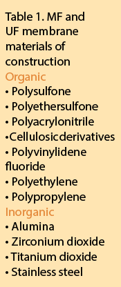
In addition to fouling, membranes can be attacked by certain chemicals in the feedwater, depending on the membrane materials of construction. MF and UF membranes can either be constructed of organic polymers or inorganic materials, whereas NF and RO membranes are all organic polymers only.
Table 1 contains a list (by no means complete) of materials of construction for MF and UF membranes. The salt rejection requirements of NF and RO membranes significantly limit the polymer selection to cellulose acetate, cellulose triacetate, or several complex cross-linked polyamide polymers produced in a thin-film composite construction. This salt-rejecting polymer is deposited on a polysulfone or polyethersulfone substrate layer by an interfacial polycondensation reaction. Although these polymers (particularly the thin-film composites) are very chemically resistant, they are more susceptible to chemical attack than the MF and UF polymers.
Waterborne contaminants
Membrane treatment, in general, involves the removal (or inactivation) of contaminants that are considered undesirable (or unacceptable) for the intended use of the water. Contaminants can be organized into specific classes (see Table 2).
Spiral-wound membranes
The vast majority of reverse osmosis and nanofiltration membrane elements in use today are of spiral-wound configuration (see Figure 1). The popularity of this configuration can be attributed to the following:
- High packing density (membrane area per element volume)
- Extensive development and manufacturing experience
- Most competitive pricing ($/gallon/day)
- Six major manufacturers located in the US

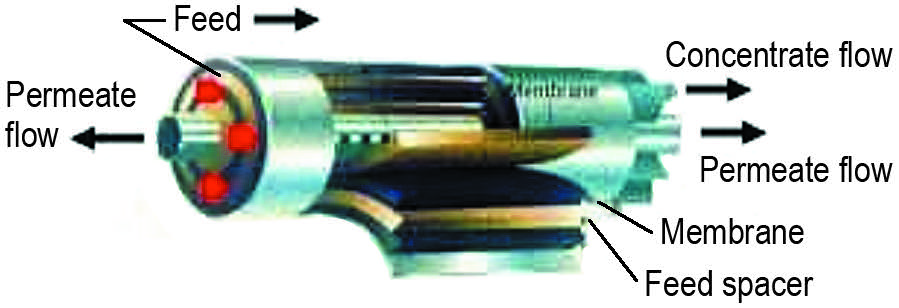
The spiral-wound membrane element configuration is susceptible to fouling, primarily due to the close spacing of the membrane layers and the fact that it cannot be backwashed to facilitate membrane cleaning. As a result, in cases where feedwaters may contain significant concentrations of fouling materials, extensive pretreatment may be required.

Feedwater characteristics
If the feedwater supply is municipally treated drinking water from a groundwater source, it will typically be low in suspended solids, organic contaminants and microorganisms; however, it will likely contain relatively high concentrations of slightly soluble salts, such as calcium carbonate. These supplies also often contain iron, which, while in the groundwater, is usually in the soluble ferrous form (Fe+2), but once exposed to air and disinfection (e.g., chlorination), becomes the insoluble ferric form (Fe+3). Where there’s iron, there’s usually at least a small quantity of manganese, which can also cause membrane fouling. Calcium carbonate scaling must be minimized, normally utilizing one (or both) of the following approaches:
a) Softening. Special cation exchange resins are employed as a pretreatment technology to exchange the calcium ion in the water with sodium ion on the resin. When the resin has exchanged as much calcium as its capacity allows, it must be taken offline, and automatically regenerated using sodium (or potassium) chloride brine.
b) pH adjustment. By lowering the pH of the feedwater to 6.0, 80 percent of the bicarbonate ion (HCO3–) is converted to carbon dioxide (CO2) and water. The carbon dioxide gas can then be air scrubbed or removed with a special degasification membrane.
Iron (and to a lesser extent, manganese) can be removed by oxidation to ensure that all of the ferrous iron is converted to the insoluble ferric form, followed by filtration. A number of technology choices are available to accomplish this. If the municipal supply is from a surface water source (reservoir, ocean, lake, river), it usually has less saturated salts, but is typically higher in the other classes of contaminants. To protect the RO or NF spiral membrane, it often requires some suspended solids filtration; however, because of the prevalence of calcium carbonate in virtually all fresh water supplies, it will likely require softening or pH adjustment also. As almost all potable water supplies in the US and many other countries contain a chlorine compound for disinfection, and because the vast majority of RO membrane elements utilize the thin-film composite polymer, chlorine must be removed to prevent oxidation of the polymer, which can result in permanent, irreversible damage. This can be accomplished with an activated carbon filter, or by adding a reducing agent, such as sodium bisulfite (NaHSO3). Obviously, it is imperative that a complete water analysis be obtained in order to identify which (and how much) of the classes of contaminants are present. This analysis, of course, will dictate the pretreatment technologies required. Because no two water sources on this planet are identical in terms of chemical analysis, it is impossible to predict exactly which contaminants (and how much) will be present without an analysis. Other sources of feedwater, such as wastewater or processing inside a manufacturing operation, present particular pretreatment challenges.

System design
Figure 2 is an illustration of a complete membrane processing system (or a single membrane element). Note that the feed stream enters the system (or membrane element), and as the stream passes along and parallel to the surface of the membrane under pressure, a percentage of the water is forced through the membrane polymer producing the permeate stream. Contaminants are prevented from passing through the membrane based on the polymer characteristics. This contaminant-laden stream exits the membrane system (or element) as the concentrate stream, also known as the brine or reject.
The permeate rate of a given membrane element cannot be changed without varying the applied pressure or temperature. Recovery, however, can be easily changed by varying the feed flowrate to the element, and this is one of the variables that is controlled by the system designer. The effect of recovery on system performance is important. As recovery is increased, the flowrate of the concentrate stream diminishes; all contaminants that are rejected by the membrane and left in the concentrate stream become much more concentrated. The effect of increasing recovery upon the concentration of contaminants in the concentrate stream is illustrated in Figures 3 and 4. For wastewater treatment and many manufacturing applications, the minimum recovery is usually higher than 80 percent.

One way to understand ‘concentration factor’ is to think in terms of the evaporation or distillation process. If half of a given volume of water is distilled and the condensate recovered as pure water (permeate), this is the same concept as operating a membrane system at 50-percent recovery. Evaporation of three-fourths of the water is 75-percent recovery and so on. The advantages of operating systems at high recoveries are that the volume of concentrate is small and the flow rate of the feed pump is smaller. The potential disadvantages are numerous:
- Higher concentration of contaminants can result in precipitation and greater propensity for fouling.
- In nanofiltration and RO applications, the concentrated salts will result in higher osmotic pressure, requiring a higher-pressure pump and a more pressure-resistant system.
- Also with RO and NF, as recovery is increased, the ionic purity of the permeate decreases.
- As higher recoveries reduce the quantity of concentrate to be discharged, the higher concentration of this concentrate stream can itself present discharge problems.
The issue of recovery is definitely application specific: most water purification applications, i.e., those treating raw water to be purified for some downstream application (drinking, product manufacturing, rinsing, etc.), generally operate at relatively low recoveries, not exceeding 85 percent, even for the largest applications. In general, most water purification applications involve feedwater conductivities (TDS) that are relatively low; the one exception is seawater desalination. Usually, the larger the system, the higher its recovery. As stated earlier, wastewater treatment recoveries are rarely below 80 percent and most operate above 90-percent recovery.
Pretreatment technologies
There are a plethora of very effective technologies available to reduce the concentration of contaminants capable of fouling spiral-wound membrane elements. Quite a few have been in use for many years and are well proven. They include: media filters, cartridge filters, coagulation and precipitation processes, oil/water separators, adsorbing resins and many others. Two relatively new entrants in the field of pretreatment technologies are microfiltration and ultrafiltration. MF is the membrane technology designed for removal of suspended solids, while UF is designed to remove dissolved macromolecules (organic contaminants). These technologies are available in a wide variety of pore sizes (mainly submicron) and materials of construction, as described earlier. The most common membrane element configurations are hollow fiber and tubular. In addition to the more ‘open’ configuration (to minimize fouling), these elements can usually be backwashed. In some applications, the membranes are run in a ‘dead-end’ mode (such as with a filter cartridge) and utilize frequent ‘backpulsing’ to remove captured contaminants. Due to their finer filtration characteristics, smaller footprint and ease of automation, these technologies are becoming increasingly popular.

Conclusion
Table 3 summarizes the typical pretreatment requirements for spiral-wound RO and NF membrane elements. As the effects of fouling contaminants become more documented, it is essential that the choices of pretreatment technologies be understood and effectively applied.
 About the author
Peter S. Cartwright, P.E., CWS-VI, is President of Cartwright Consulting Company. He has been in the water treatment industry since 1974, has authored over 125 articles, presented over 125 lectures in conferences around the world and has been awarded three patents. Cartwright has chaired several WQA committees and task forces and has received the organization’s Award of Merit. A member of WC&P Technical Review Committee since 1996, his expertise includes high-technology separation processes such as RO, UF, MF, UF electrodialysis, deionization, carbon adsorption, ozonation and distillation. Cartwright is also Technical Consultant to the Canadian Water Quality Association. He can be reached by phone (952) 854-4911; fax (952) 854-6964; email [email protected] or on his website, www.cartwright-consulting.com.


