By Peter S. Cartwright, P.E.
The membrane technology of reverse osmosis has been around for many years now and is finding more and more applications in all aspects of water treatment. This technology couldn’t care less as to the source of the water to be treated; however, its performance and design requirements are significantly affected by the feedwater characteristics and intended use of the treated water.
In general, it is useful to divide the feedwater into three categories based on source:
- Raw water. Water coming from a natural source (well, river, lake, ocean) or a municipal drinking water treatment plant
- Wastewater. Water leaving an industrial or commercial facility or a sewage treatment plant
- Process water. Wastewater from within a manufacturing process
With the rapidly growing emphasis on water reclamation and reuse, it is important to understand the distinctions between these source waters and their impact on membrane system designs. This article primarily addresses the application of reverse osmosis technology to wastewater and process water. The sources of raw water supplies (even seawater) all fall within a relatively narrow range of chemical characteristics, which are well understood and present minimal design challenges. For example, to design a reverse osmosis treatment system with spiral-wound membrane elements, all of the membrane manufacturers offer a computer program that will provide someone (with some skill in the technology) the ability to design a water purification system. It is usually only necessary that this person possesses an understanding of the following feedwater parameters:
- Feedwater analysis
- Purified water quality requirements
- Total volume requirement (per day, per minute)
- Desired system recovery
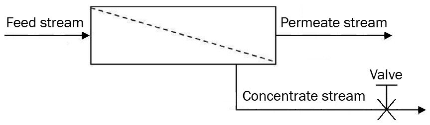
A typical membrane process is illustrated in Figure 1.
Raw water
For most water purification applications, the primary goal is to meet a specific treated water quality requirement, and system recovery is usually a secondary requirement. System recovery is that percentage of the feedwater flow that passes through the membrane and becomes permeate. Recovery is the purview of the system designer, and typically ranges from less than 50 percent for low-flow applications, up to as high as 85 percent for very large applications. The advantage of high-recovery designs is that a relatively small quantity of concentrate (that percentage of the water that does not pass through the membrane and carries away the contaminants removed from the water supply) is discharged. Because of these lower flowrates, other advantages include a smaller feed pump and usually smaller pipe sizes. The primary disadvantage of high recovery is that the concentration of contaminants in the concentrate stream increases dramatically as recovery is increased. This increased concentration can result in scaling and other fouling problems on the membrane surface.
Wastewater
The primary goal here is usually to make the concentrate stream as small as possible to facilitate further treatment or disposal. As a result, recoveries are generally set very high, typically above 90 percent. Additionally, in the case of most industrial wastewater streams, the water characteristics (contaminant type and concentrations) are usually one-of-a-kind. This, combined with the extremely high recoveries, requires that testing be performed in order to develop system design data. This testing can take the form of cell testing, applications testing and/or pilot testing, but is absolutely essential in industrial wastewater applications. None of the available computer programs is capable of designing an effective wastewater treatment system.
For reverse osmosis, the ionic concentration increases (resulting from the effects of high recovery), and since the reverse osmosis mechanism involves a percent rejection of salts (typically above 90 percent), this means that a percentage (albeit small) of the salts concentration at the membrane surface passes through the membrane into the permeate stream (100 minus percent rejection). As the concentration of salts increases from higher recovery operation, a higher quantity passes through the membrane, thereby lowering the quality of permeate. This high recovery also produces a high osmotic pressure in those streams with significant salts content. Osmotic pressure is basically the resistance of an ionic solution to being pumped through a reverse osmosis or nanofiltration membrane, and is a function of both the kind of salts and their concentration. In typical seawater (35,000 ppm TDS), a minimum of 400 psi pressure is required to overcome the osmotic pressure of the feed solution, and to produce the first drop of permeate.
It is important to remember that the concentration of contaminants seen by the membrane is roughly the arithmetic average of the feed and concentrate streams. Under high-recovery conditions, the concentrate stream concentration is extremely high, which, of course, will make the average concentration high. This means that the TDS of the feedstream does not have to be particularly high to result in a high osmotic pressure condition. One of the outcomes of a test program is the determination of osmotic pressure as a function of recovery for a given wastestream. Typically, higher pressure pumps are employed for significant osmotic pressure effects, up to 1,000 psi (68 bar).
For wastewater applications, an important parameter is the choice of the ultimate discharge of the concentrate stream. Depending upon the situation, options include evaporation to dryness, collection in an ion exchange resin or other adsorptive medium, or simply removing this stream for disposal.
Process water
Of the three general applications for membrane technologies, chemical processing is the most complex and diverse. Membranes are used for applications where certain ’contaminants‘ are separated from each other into separate streams (fractionation) and then one or more possibly recovered for reuse. Examples include the recovery of lactalbumin protein from cheese whey, or when rinse waters in food processing are treated for concentration and recovery of a desirable component separated from an undesirable one.
Testing requirements
With regard to wastewater and process water applications, it is imperative that every stream be tested to identify the following design factors:
- Optimum membrane element configuration
- Total membrane area
- Specific membrane polymer
- Optimum pressure
- Maximum system recovery
- Flow conditions
- Membrane element array
- Pretreatment requirements
Specific properties of feedstreams that influence these design factors include:
- Stream chemistry
– Total solids content
– Suspended (TSS)
– Dissolved organic (TOC, MBAS, COD, BOD)
– Dissolved inorganic (TDS) - Chemicals of concern
-Oxidizing chemicals
-Organic solvents (particularly aromatic hydrocarbons)
-Saturated solutes - pH
- Operating temperature
- Osmotic pressure as a function of system recovery
- Variation in chemistry as a function of time
- To generate the necessary design data, the following testing options are available.
Cell testing
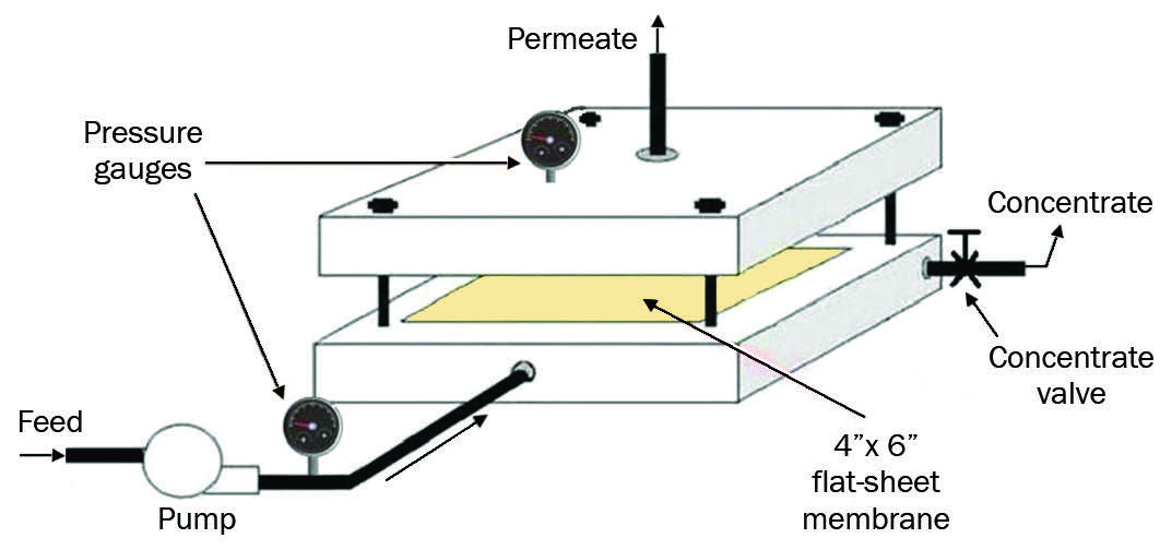
A typical cell-testing device is illustrated in Figure 2. Cell test devices are available for purchase (or testing through a consulting engineering firm skilled in the art), which evaluate small sheets of membrane candidates on the stream to be processed. Typically, the sheet is placed between two stainless steel plates, and the test stream pumped across the membrane surface at a selected pressure and flowrate. The permeate is collected and analyzed for degree of solute separation, possible effect of the stream on the test membrane, and other properties. Cell testing requires only small volumes of test solution and several membranes can be evaluated in a short period of time. The cell test approach is useful as an initial step, primarily to select one or more membrane candidates for further evaluation; however, an actual system design cannot be developed from this test.
Applications Testing
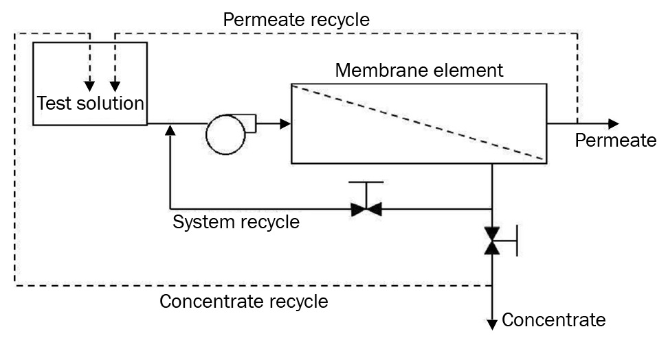
Figure 3 illustrates an applications test schematic. Applications testing utilizes a full-sized membrane element in a test unit capable of operating similarly to a production unit. Since the data from this testing will be used to scale up the design to full size, it is essential that the membrane element manufacturer supplies an element capable of this scale up.
The applications test equipment should be designed so that very high recoveries can be achieved without compromising the flowrates required to produce turbulent flow, for example. This requires that the pump be capable of not only producing the desired pressure, but also the flowrate to accomplish the minimum crossflow velocity across the membrane surface.
Materials of construction are an important consideration in testing considerations: 316L stainless steel is essential for most applications requiring pressures in excess of 60 psi (4 bar); below that, schedule 80 PVC is usually sufficient. For high chloride streams, special alloys may be required.
Applications testing is capable of generating complete design data for a full-sized system. An applications test can be run on as little as 50 gallons (200 liters) of test stream, and after setup, can be completed in one hour or less for each membrane element tested.
A typical applications test is run as follows:
- To establish control conditions, high-quality water (tap water or water treated with RO or DI) is run into the system at low recovery. Data are recorded for these control conditions.
- Feedwater is then run into the unit initially set at low recovery, and after stabilization (usually less than five minutes), data are taken: feed pressure, pump pressure (pump discharge), system pressure (at the exit of the membrane upstream of the concentrative valve), recycle pressure, flowrates (usually feed, recycle and permeate) and recycle stream temperature. The system recovery is then increased incrementally while adjusting the recycle to ensure that the correct crossflow velocity is maintained.
- At each recovery, in addition to the collection of flow and pressure data, analytical samples may be taken for performance evaluation. Of course, the choice of chemical parameters to be measured depends upon the separation goals of the test. It is unusual for system recoveries to exceed 95 percent; however, that also depends upon the goals of the testing, and it is possible to run a well-designed test unit up to 99-percent recovery. Once the optimum conditions have been established, such as operating pressure and maximum system recovery, the normalized performance data will enable the test engineer to determine the total membrane area required for the full-sized system.
Pilot Test
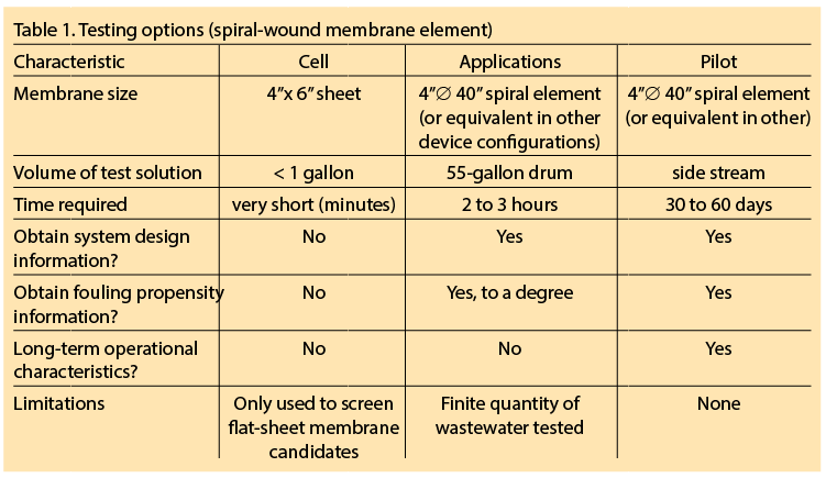
Usually, this involves placing a test machine (such as that used for the applications test) in the process, operating continuously on a sidestream for a minimum of 30 days. The optimum run conditions (recovery, pressure, flowrates, etc.) are maintained during the testing, and pretreatment requirements can usually be obtained during this testing. Table 1 summarizes the important characteristics of these testing options.
Conclusions
Although water purification applications currently dominate the RO membrane technology market, the potential for membrane separation technologies in wastewater and processing applications is basically untapped. To realize this potential, it is imperative that any candidate stream be thoroughly tested. This requires knowledgeable, experienced personnel to run and interpret test results on well-designed testing equipment.


